Modern electronics are expected to do more than ever before — in smaller spaces, under harsher conditions, and with greater reliability than previous generations of devices ever achieved. Meeting these demands has pushed engineers to look beyond traditional circuit board designs and embrace more innovative solutions. One of the most significant of these innovations is rigid flex PCB assembly — a technology that combines the best qualities of both rigid and flexible circuit boards into a single, highly capable electronic package.
In this article, we’ll explore what rigid flex PCB assembly is, how it works, where it’s used, what makes it challenging to manufacture, and why it’s becoming an increasingly popular choice for advanced electronics design.
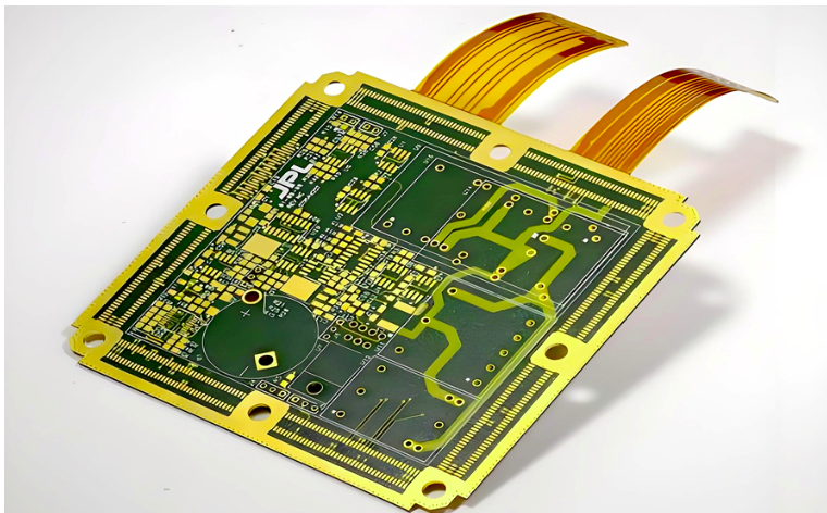
What Is Rigid Flex PCB Assembly?
A rigid flex PCB is a hybrid circuit board that combines rigid board sections and flexible circuit sections into a single integrated structure. The rigid sections provide a stable platform for mounting components and connectors, while the flexible sections act as built-in interconnects — replacing the separate cables or connectors that would otherwise be needed to link different parts of a device.
Rigid flex PCB assembly is the process of populating these hybrid boards with electronic components and soldering them in place to create a fully functional electronic assembly.
To understand why this is significant, consider a traditional electronic device that uses separate rigid PCBs connected by ribbon cables or wire harnesses. Each connection point is a potential failure point — cables can fray, connectors can work loose, and the added bulk of cables takes up valuable space. A rigid flex PCB eliminates many of these issues by integrating the connections directly into the board structure itself.
How Is a Rigid Flex PCB Constructed?
Rigid flex PCBs are more complex in construction than either rigid or flexible boards alone. A typical rigid flex PCB consists of multiple layers that may include:
Rigid Sections: These areas of the board use standard rigid PCB materials — typically FR4 fiberglass — and can support the same components and features as any conventional PCB. Multiple rigid sections can exist within a single rigid flex design, connected by flexible segments.
Flexible Sections: These areas use flexible polyimide (PI) film as the base material, with thin copper traces laminated onto the surface. The flexible sections are designed to bend, fold, or flex repeatedly without cracking or breaking the copper traces.
Adhesive and Coverlay Layers: The flexible sections are protected by a coverlay — a flexible equivalent of the solder mask used on rigid boards — that insulates and protects the copper traces while still allowing the board to flex.
Stiffeners: In some designs, stiffeners — additional layers of rigid material bonded to specific areas of the flexible section — are added to provide local support for connectors or components that cannot tolerate flexing.
The result is a single unified structure that can be folded, bent, or shaped during installation to fit precisely within the available space inside a device — like an electronic origami.
The Rigid Flex PCB Assembly Process
Assembling rigid flex PCBs requires careful handling and specialized processes due to the delicate nature of the flexible sections. Here’s how the process typically works:
Step 1: Design Review and DFM Analysis Rigid flex PCB design is significantly more complex than standard PCB design, and even small errors can be expensive to correct. Before assembly begins, a thorough Design for Manufacturability (DFM) review is conducted to identify any potential issues with the design — including bend radius violations, component placement too close to flex zones, or insufficient strain relief at the transition between rigid and flexible sections.
Step 2: PCB Fabrication The bare rigid flex PCB is fabricated using a specialized process that combines rigid and flexible laminate materials. The rigid and flexible layers are laminated together under precisely controlled heat and pressure, drilled, plated, etched, and finished — a more complex and time-consuming process than fabricating either a rigid or a flexible board alone.
Step 3: Preparation for Assembly Before components are placed, the rigid flex board is carefully inspected for any fabrication defects. Panels may be prepared with custom fixtures or carriers to support the flexible sections during assembly and prevent them from moving or bending in ways that could interfere with the placement or soldering processes.
Step 4: Solder Paste Application Solder paste is applied to the component pads on the rigid sections of the board using a stencil printer. Special care is taken to ensure the board is properly supported during this step — the flexible sections must not bend or deflect while the stencil is in contact with the board, as this could lead to inconsistent paste deposits.
Step 5: Component Placement Automated pick-and-place machines place components onto the rigid sections of the board. Because components are never placed directly onto the flexible sections — which are reserved for interconnects — placement is focused entirely on the stable rigid areas. However, the unusual shape of a rigid flex panel requires careful programming of the pick-and-place equipment and, in many cases, the use of custom support fixtures to hold the board flat during placement.
Step 6: Reflow Soldering The populated board passes through a reflow oven, where the solder paste melts and forms permanent solder joints. The reflow temperature profile must be carefully controlled — both the rigid and flexible sections of the board are present simultaneously, and they have different thermal characteristics. Overheating the flexible sections can damage the polyimide material or cause delamination.
Step 7: Inspection After reflow, the assembled board undergoes thorough inspection. Automated Optical Inspection (AOI) checks the rigid sections for soldering defects. For components with hidden solder joints — such as BGAs — X-ray inspection is used. The flexible sections are also inspected for any signs of damage, delamination, or cracking of the copper traces.
Step 8: Functional Testing The assembled rigid flex PCB is tested to verify that it functions correctly. This may include in-circuit testing (ICT), functional testing under simulated operating conditions, and in some cases, flex cycling tests — repeatedly bending the flexible sections a specified number of times to verify that the board will survive the mechanical stresses of its intended application.
Step 9: Forming and Folding In many applications, the rigid flex PCB is designed to be folded or shaped into a specific three-dimensional form during installation. This forming step may be carried out by the assembly house before delivery, or it may be left to the customer to perform during product assembly. Either way, it must be done carefully — bending the flexible sections too sharply or in the wrong direction can crack the copper traces and destroy the board.
Key Advantages of Rigid Flex PCB Assembly
The added complexity and cost of rigid flex PCBs are justified by a compelling set of advantages:
Space and Weight Savings: By eliminating separate cables, connectors, and multiple discrete PCBs, rigid flex designs significantly reduce the overall size and weight of an electronic assembly. This is critical in applications like wearable devices, drones, and aerospace equipment where every gram matters.
Improved Reliability: Every connector and cable junction in a traditional multi-board design is a potential point of failure. Rigid flex PCBs eliminate many of these junctions, resulting in assemblies that are inherently more reliable — particularly in high-vibration environments like automotive and aerospace applications.
Three-Dimensional Design Freedom: Rigid flex PCBs can be folded and shaped to fit precisely within irregular or constrained spaces — spaces that a flat rigid board simply cannot occupy. This gives product designers far greater freedom to optimize the internal layout of their devices.
Simplified Assembly: While the PCB itself is more complex, the overall product assembly process can be simpler and faster. With interconnects built into the board, there are fewer cables to route, fewer connectors to attach, and fewer opportunities for assembly errors.
Better Signal Integrity: Eliminating connectors and cables between PCBs reduces impedance discontinuities and signal loss, improving electrical performance — particularly important in high-speed and high-frequency applications.
Challenges of Rigid Flex PCB Assembly
Despite its advantages, rigid flex PCB assembly presents real manufacturing challenges:
Design Complexity: Designing a reliable rigid flex PCB requires specialized knowledge of both rigid and flexible board design rules, bend radius calculations, layer stack-up considerations, and the mechanical behavior of flexible materials. Mistakes at the design stage are expensive to correct.
Higher Manufacturing Cost: Rigid flex PCBs cost more to fabricate and assemble than equivalent rigid board designs. The specialized materials, additional processing steps, and lower production yields all contribute to higher unit costs. This cost premium is usually justified by the performance and reliability benefits, but it must be factored into project budgets.
Specialized Handling Requirements: The flexible sections of a rigid flex PCB are delicate and must be handled with care throughout the assembly process. This requires trained personnel, appropriate fixtures and carriers, and careful process design.
Limited Rework Options: Reworking a rigid flex PCB — replacing a misplaced component or repairing a solder joint — is more difficult than on a standard rigid board. The proximity of the flexible sections to the rigid assembly areas, combined with the heat sensitivity of polyimide materials, limits the options available for rework.
Where Is Rigid Flex PCB Assembly Used?
Rigid flex PCBs are found in some of the most demanding and innovative electronic products on the market today:
Medical Devices: Implantable devices, surgical tools, diagnostic equipment, and wearable health monitors all benefit from the compact, reliable, biocompatible designs that rigid flex technology enables.
Aerospace and Defense: Avionics, satellite systems, military communications equipment, and guided munitions use rigid flex PCBs for their exceptional reliability in extreme environments.
Consumer Electronics: Smartphones, tablets, laptops, smartwatches, and foldable devices use rigid flex PCBs to achieve their thin, compact designs and to connect displays, cameras, and batteries within tightly constrained spaces.
Automotive Electronics: Advanced driver assistance systems (ADAS), infotainment systems, and electric vehicle battery management systems use rigid flex designs to survive the vibration, temperature extremes, and space constraints of the automotive environment.
Industrial Equipment: Robotics, industrial cameras, and precision measurement instruments rely on rigid flex PCBs for reliable interconnection in compact, rugged packages.
Conclusion
Rigid flex PCB assembly represents one of the most sophisticated and capable technologies in modern electronics manufacturing. By combining the component-mounting strength of rigid boards with the space-saving, reliability-enhancing qualities of flexible circuits, rigid flex PCBs enable product designs that simply wouldn’t be possible with conventional board technology. As electronic devices continue to shrink, gain capability, and operate in ever more demanding environments, the demand for rigid flex solutions will only continue to grow. For companies looking to leverage this technology, partnering with an experienced China rigid flex PCB assembly provider offers access to the advanced manufacturing expertise, specialized equipment, and rigorous quality processes needed to produce rigid flex assemblies that perform reliably in even the most challenging applications.